ClearGauntlet-PCB-rev B
PCB - Schematics Design for VR Gloves
A breakout board for ClearGauntlets, aimed at improving cable management and minifying electronics of VR Gloves.

Specs
The board has the following I/O:
- 1 ESP 32 V1
- 10 potentiometers, each requires 1 3.3V pin, 1 GND, 1 Analog pin.
- 5 servo motors, each requires 1 5V pin, 1 GND, 1 Analog pin.
- 2 pushed bottons
- 1 joystick (5 pins)
- 1 power JST connection (3 pins: 1 5V and 2 GND)
Pin details

Assembly
To assemble the board, you'll need - 30 pins Female Dupont Connectors, 2.54mm pitch (2x 15-pin). This is for holding the ESP-32 - 15 x 3 pins Male Dupont Connectors, 2.54mm pitch, for connecting potentiomers, servos) - 2 x 2 pin Male Dupont for push buttons and 5 pin Male Dupont for Joystick - 1 ESP32
It's all just through-hole soldering, so it goes pretty quick once you have the parts. Use the CAD renders as a guide.
You will also probably want to create a 2-pin 5V USB cable like this one:

It's just power, and ground, and goes into the 5V/GND JST connector next to the ESP32.
You'll also need to bodge that 5V in pin to the Vin pin that goes to the ESP32
Demo Picture
Plain PCB

Assembled PCB

ClearGauntlet - Joystick PCB
Joystick PCB - Schematics Design for interfacing between Joycon's joystick and main PCB.
Motivation: To allow for joystick control in games that support/require it, we're kludging a Nintendo Switch Joystick onto our glove. Since the flex cable is very short and flimsy, we want to create a small PCB board to hold, and connect pins to the main PCB more reliably.
Components
Joystick
This joystick is the 3rd party replacement for the joycon.

Schematics
The measurement of the joystick in mm:

Adapter
We need a 5-pin (0.5mm spaced) adaptor to connect on the board and split the pins to the standard dupont spacing (2.56 mm).
This model can be found on Mouser.

PCB
3D model

Assembly
The joystick will be mounted on the backside of the PCB either by through holes or hot glued it directly. Then, the flex cable will connect to the adaptor. A horizontal 5-pin male dupont will be place at the J2 and run a wire to the main PCB. The idea is to make PCB-joystick as a module which will be placed on the side of the index finger.# CG Proto 2 Wiring Guide
Assembling the PCB
The PCB assembly should be pretty straightforward. It is simply a breakout board for many of the ESP32’s connections.
You will need fifteen three-pin male dupont connectors, two fifteen-pin female dupont connectors, one 2x4-pin female dupont connector, a 1000uF capacitor, a 680ohm resistor, and a four-pin male dupont connector with the second and fourth pins cut off.
Wiring the finger modules
You can get started on wiring up your potentiometers once you’ve reached this stage of printing and assembly.
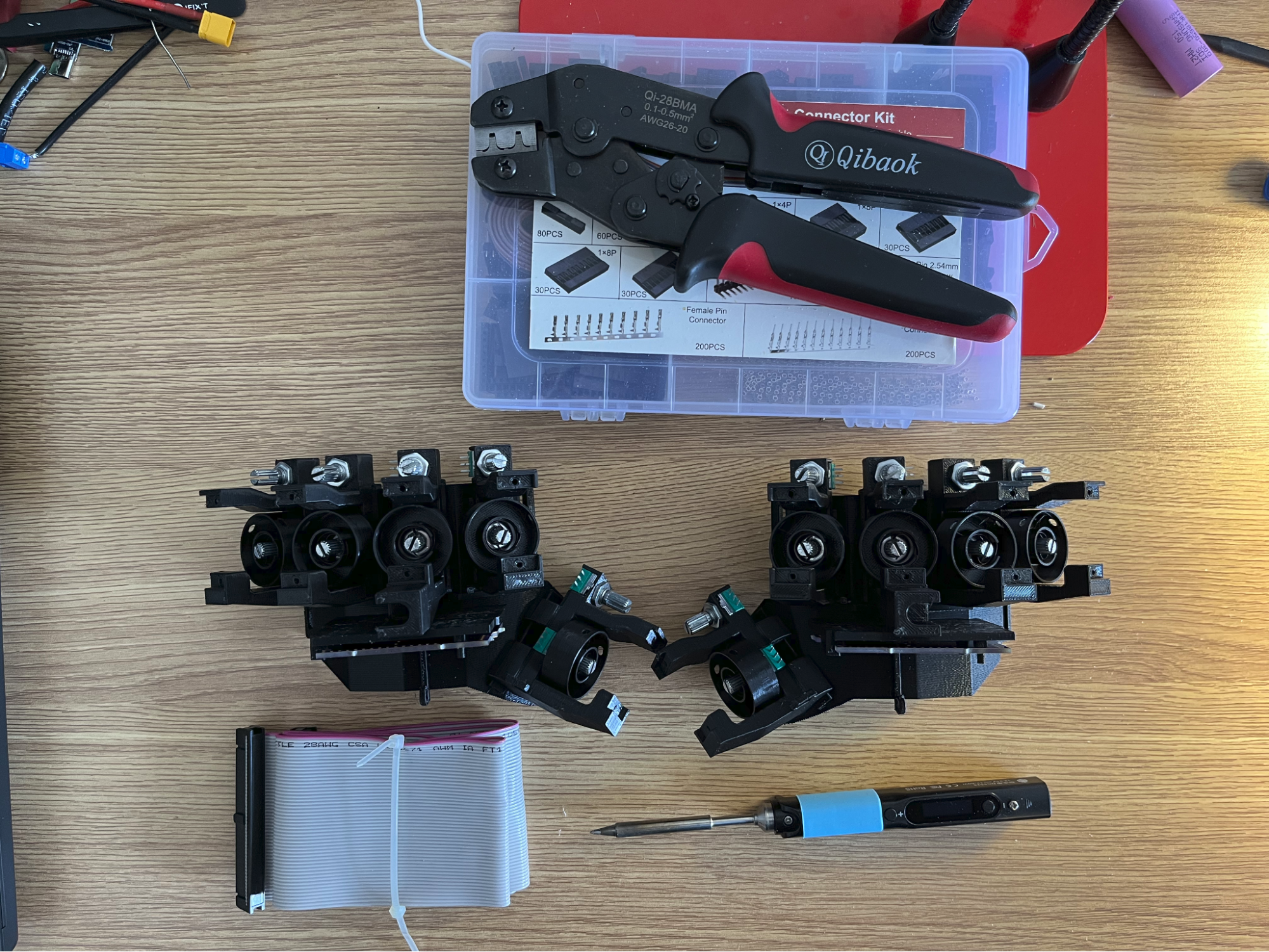
Figure 1: Tools required for finger module wiring
For each hand, you’ll need ten three-pin dupont connectors, a length of ribbon cable (I like to use salvaged IDE cables), a crimping tool, and a soldering kit.
Cut twenty three-pin cables to the lengths found in Table 1. Crimp them with three pin female dupont connectors.
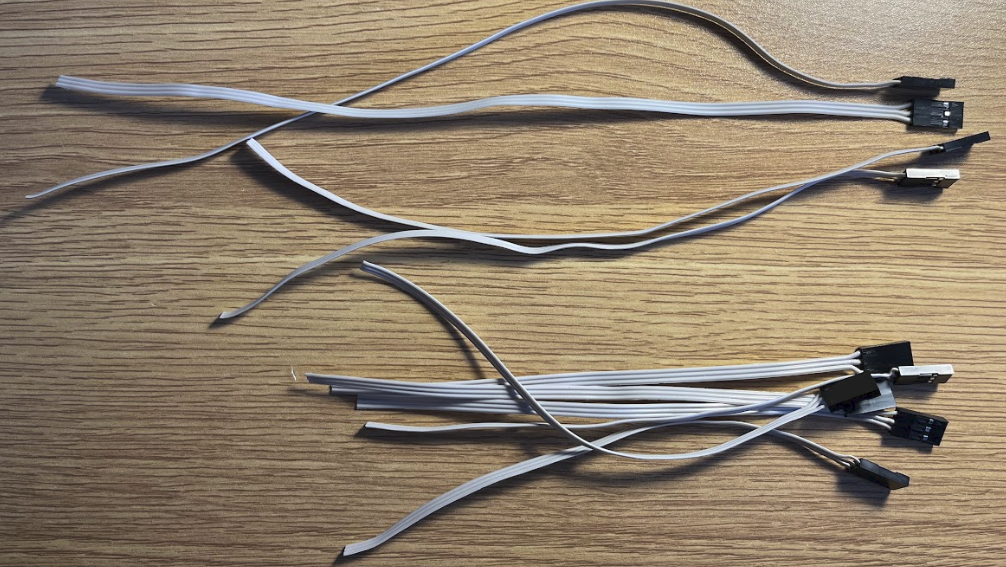
Figure 2: Cables cut to length
Table 1: Rotation of spools and length of cable
| Finger | Spool Rotation | Curl Cable Length | Splay Cable Length |
|---|---|---|---|
| Right Thumb | Clockwise | 8” | 8” |
| Right Pointer | Counterclockwise | 7” | 7” |
| Right Middle | Counterclockwise | 6” | 6” |
| Right Ring | Clockwise | 5” | 5” |
| Right Pinky | Clockwise | 6” | 6” |
| Left Thumb | Counterclockwise | 8” | 8” |
| Left Pointer | Clockwise | 8” | 8” |
| Left Middle | Clockwise | 6” | 6” |
| Left Ring | Counterclockwise | 5” | 6” |
| Left Pinky | Counterclockwise | 5” | 6” |
You will have to cross one of the wires, since the middle pin of the breakout PCB is the VCC pin and the middle pin of the potentiometer is the signal pin. The recommended pinout of the cables is shown below.
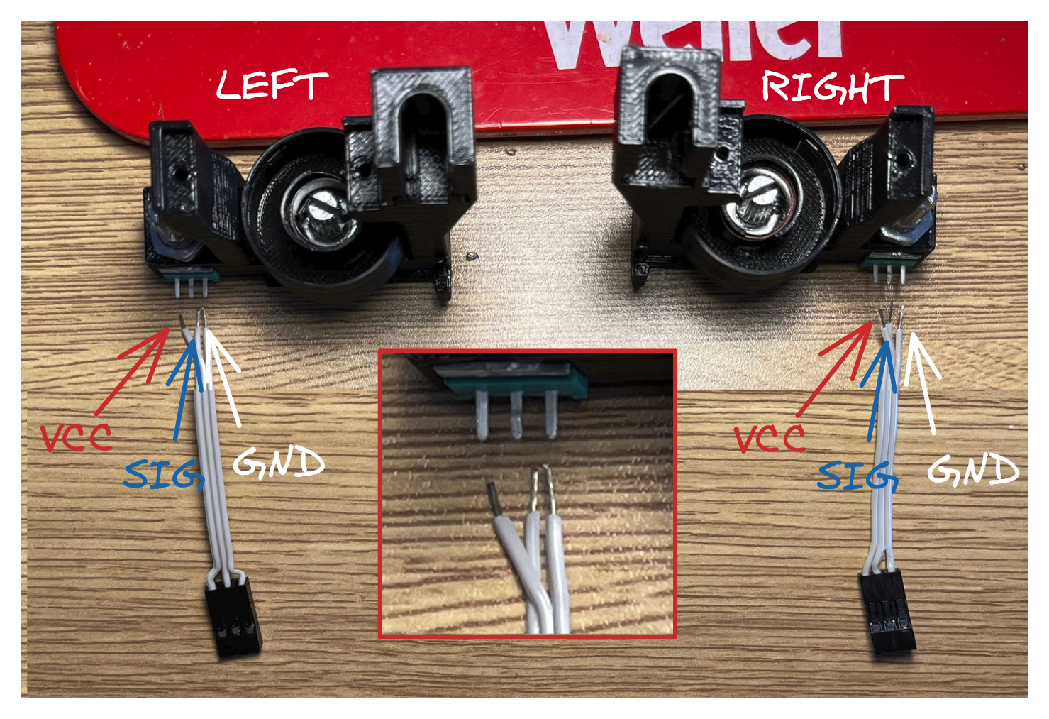
Figure 3: Soldering guide for module cables
On the left hand, the pair of wires farthest from your wrist should be crossed, and on the right, the pair of wires closest to your wrist should be crossed. This ensures a consistent pinout across the entire pair, and will make it easier to configure in software later. Both the curl and splay potentiometers should be soldered this way. (Because the spin direction of the potentiometers is reversed on the pointer and middle finger, the firmware will need to be configured to reverse the measured value later)
My technique is this: Tin the ends of the wire, then heavily tin the end of the potentiometer. Use a helping hand to hold the module, then with your hands, hold the wires and soldering iron. Solder each wire one at a time, and give the module a chance to cool down between each pin soldering to prevent burning out the potentiometer.
When you are finished, you’ll have something that looks like this:
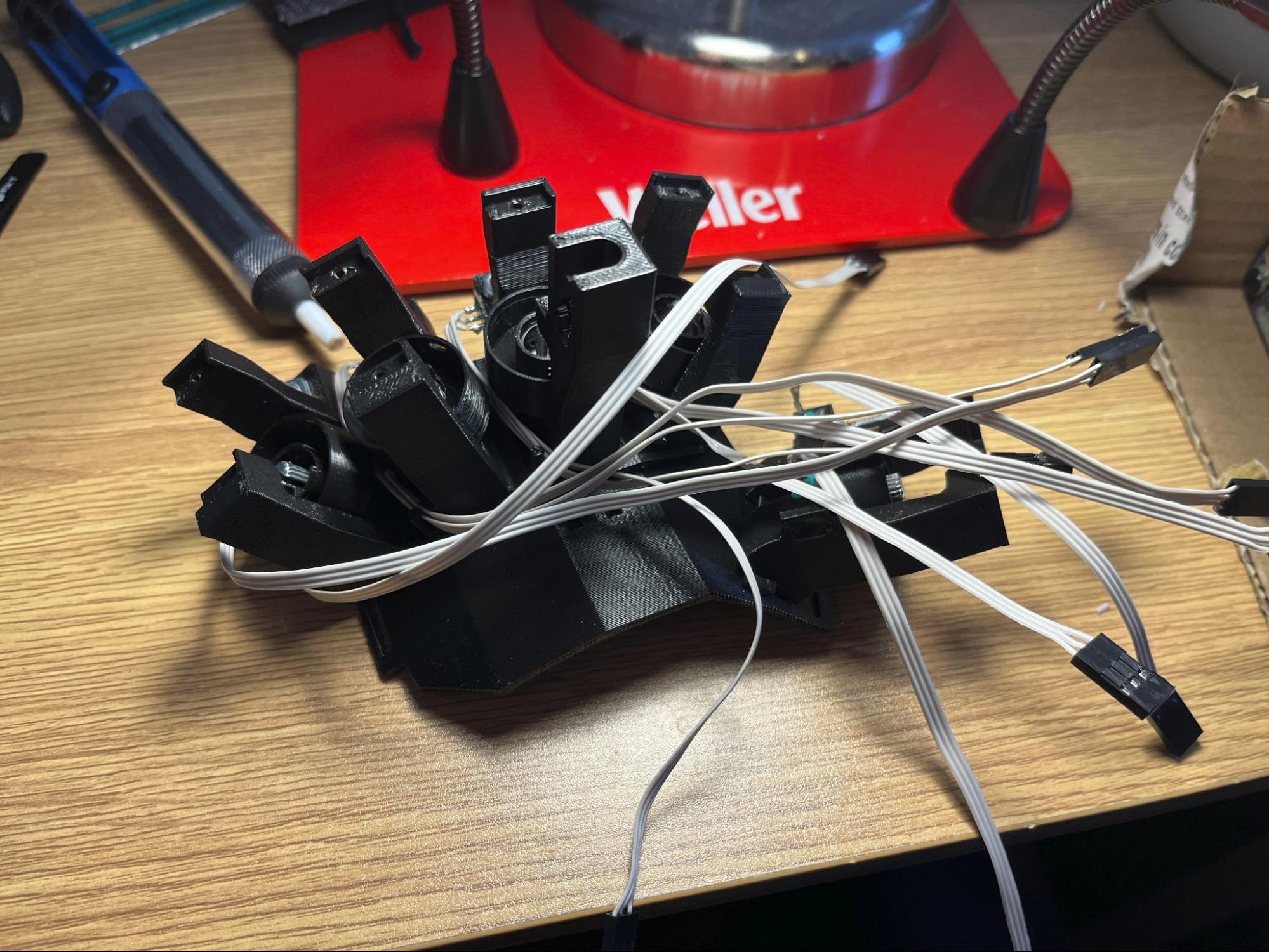
Figure 4: Soldered finger modules with un-managed cables
Organizing the wires is a little… chaotic. I usually just try to corral them together as much as possible towards the pinky, plug ‘em in, then try to zip tie them in place. I’m still working on the cable lengths and am hoping to add more cable channels and perhaps update the PCB to alternate curl/splay to reduce the amount of weird overlap we have.
But, when you’re finished, you should have something that looks like this:
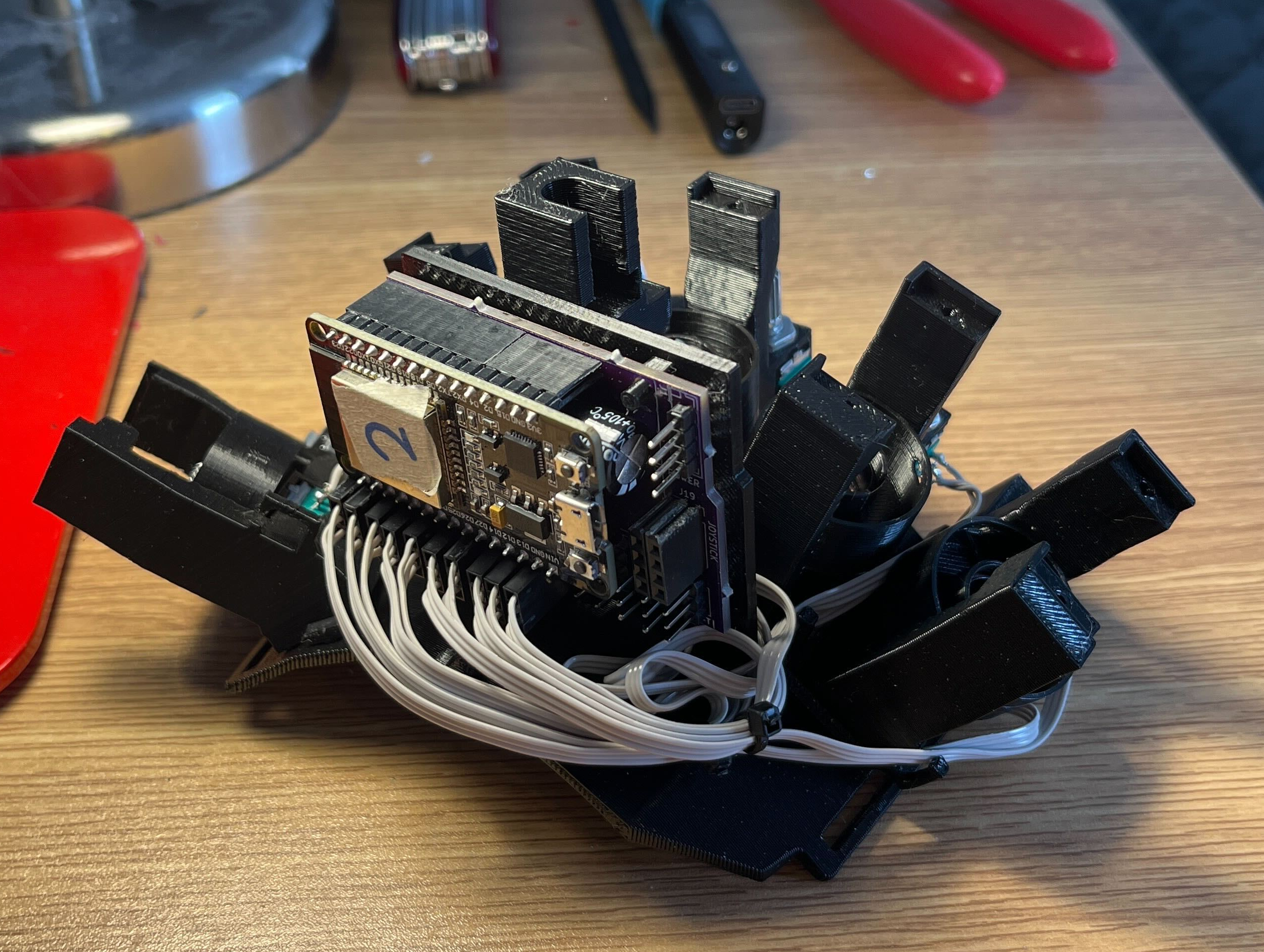
Figure 5: Completed Finger Tracking Module
Calibrating and Installing the Servos
TODO